Today, I will be talking about Cisco UCS NetFlow configuration via GUI, including its limitations and differences compared to the configuration via CLI. I will also walk you through the configuration steps, showing how to turn NetFlow on and start getting visibility into your UCS traffic!

Cisco UCS NetFlow Fundamentals
As you might already know, Cisco UCS Manager relies on NetFlow-capable adapters, such as Cisco UCS VIC 1240, Cisco UCS VIC 1280, and Cisco UCS VIC 1225 to communicate with the routers and switches that collect and export flow information.
The NetFlow support for Cisco UCS got added in version 2.2(2c) and can be configured either in the GUI or the CLI. While this blog will focus solely on the GUI version, my colleague Austin did a great job explaining the Cisco UCS NetFlow Configuration via CLI.
There is one primary difference between the two NetFlow configuration methods. In the Cisco UCS Manager GUI, the networking properties are defined in an exporter interface that is included in the profile. In the Cisco UCS Manager CLI, however, the properties are defined in the profile.
What are the limitations?
According to the Cisco UCS documentation, NetFlow monitoring is not supported:
- on the Cisco UCS 6100 Series Fabric Interconnect;
- in vNIC template objects;
- with usNIC, the Virtual Machine queue, or Linux ARFS.
VLAN requirements:
- VLANs must be defined as an exporter interface before they can be used with a flow collector.
- All VLANs must be public and must be common to both fabric interconnects.
- PVLANs and local VLANs are not supported for service VLANs.
Cisco UCS NetFlow configuration: step by step
1. Enable NetFlow on your UCS deployment by navigating to the LAN tab, NetFlow > General page and checking the radio button.
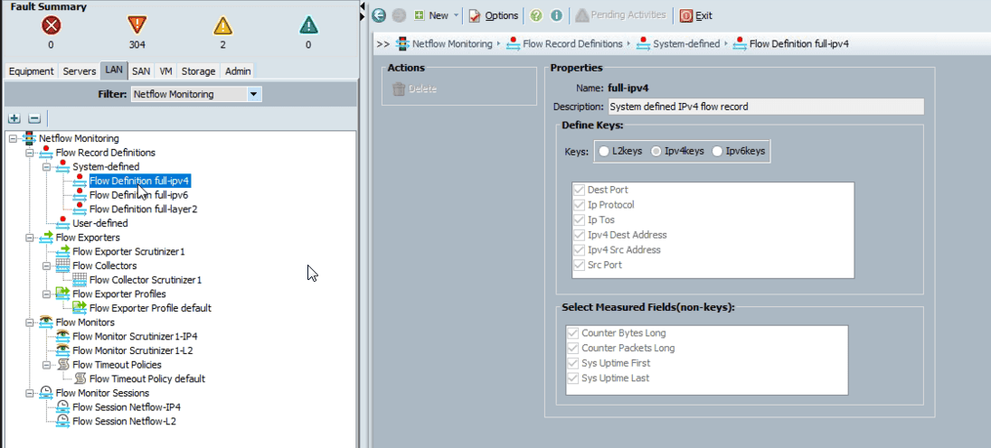
2. Define a flow record:
- In the Navigation pane, click the LAN tab and then NetFlow Monitoring.
- Right-click Flow Record Definitions and select Create Flow Record Definition.
- In the Create Flow Record Definition dialog box, enter the record name and description, then select the key you would like to use, such as IPv4, IPv6, or Layer 2 Switched. After that, use the checkbox for the non-key fields to be included for the flow:
3. Define an Exporter Profile:
- Proceed to the LAN > NetFlow Monitoring > Flow Exporters > Flow Exporter Profiles page and select Flow Exporter Profile default.
- Click Add in the Properties area, which is to the side of the Exporter Interface(s) table.
- Populate the following fields in the Create Exporter Interface dialog box:
- Name
- Description
- VLAN that you want to associate with the exporter interface
- Fabric A Source IP
- Fabric A Subnet Mask
- The subnet mask for the exporter interface on fabric A
- Fabric B Source IP
- Fabric B Subnet Mask
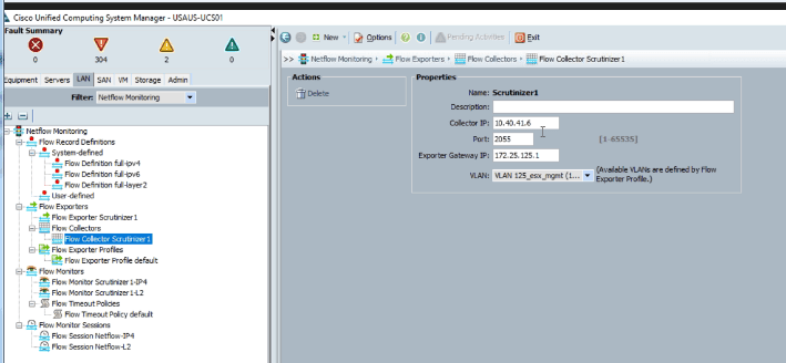
4. Define a Flow Collector:
- In the LAN > NetFlow Monitoring > Flow Collectors tab, click Add at the side of the Flow Collectors table.
- Populate the Create Flow Collectors dialog box with the name and description of the flow collector, as well as its IP address, port, Exporter Gateway IP, and VLAN.
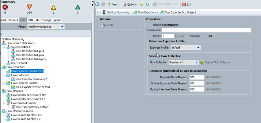
5. Define a Flow Exporter:
- Go to the LAN > NetFlow Monitoring > Flow Exporters and select Create Flow Exporter.
- Complete the following fields in the dialog box:
- Name
- Description
- DSCP
- Version
- Exporter Profile
- Flow Collector
- Template Data Timeout
- Option Exporter Stats Timeout
- Option Interface Table Timeout
6. Define a Flow Monitor:
- Access the LAN > NetFlow Monitoring > Flow Monitors pan and select Create Flow Monitor.
- In the Create Flow Monitor dialog box, enter the fields for:
- Name
- Description
- Flow Definition
- Flow Exporter 1
- Flow Exporter 2
- Timeout Policy
7. Define a Flow Monitor Session:
- Proceed to the LAN > NetFlow Monitoring > Flow Monitor Sessions and click Create Flow Monitor Session.
- Complete the fields in the dialog box:
- Name
- Description
- Host Receive Direction Monitor 1; choose the flow monitor that you want to use from the list of values, or click Create Flow Monitor to create a new one.
- Host Receive Direction Monitor 2
- Host Transmit Direction Monitor 1; choose the flow monitor that you want to use from the list of values, or click Create Flow Monitor to create a new one.
- Host Transmit Direction Monitor 2
8. Assign a Flow Monitor Session to a vNIC:
- Under the LAN > NetFlow Monitoring > Flow Monitor Sessions, select the flow monitor session that you want to associate.
- Choose the Flow Exporter Profile default and expand vNICs in the Properties area.
- Click Add at the side of the table, then choose the vNIC that you want to associate with the flow monitor session in the dialog box.
We saved the Cisco UCS NetFlow configuration changes and voilà—a few minutes later, Scrutinizer started reporting on its flows:

Don’t know where to start?
Are you struggling to get better visibility into the traffic flowing through your network? Reach out to our support team if you want to learn more or need help with configurations.