In computer science, the concept of network layers is a framework that helps to understand complex network interactions. There are two models that are widely referenced today: OSI and TCP/IP. The concepts are similar, but the layers themselves differ between the two models.
What are the network layers?
While TCP/IP is the newer model, the Open Systems Interconnection (OSI) model is still referenced a lot to describe network layers. The OSI model was developed by the International Organization for Standardization. There are 7 layers:
- Physical (e.g. cable, RJ45)
- Data Link (e.g. MAC, switches)
- Network (e.g. IP, routers)
- Transport (e.g. TCP, UDP, port numbers)
- Session (e.g. Syn/Ack)
- Presentation (e.g. encryption, ASCII, PNG, MIDI)
- Application (e.g. SNMP, HTTP, FTP)
People have come up with tons of mnemonic devices to memorize the OSI network layers. One popular mnemonic, starting with Layer 7, is “All People Seem To Need Data Processing.” But one that I’m partial to, which starts with Layer 1, is “Please Do Not Throw Sausage Pizza Away.”
The TCP/IP model is a more concise framework, with only 4 layers:
- Network Access (or Link)
- Internet
- Transport (or Host-to-Host)
- Application (or Process)
One mnemonic device for the TCP/IP model is “Armadillos Take In New Ants.”
Network Layers and Functions
For the OSI model, let’s start at the top layer and work our way down.
- Layer 7 (Application): Most of what the user actually interacts with is at this layer. Web browsers and other internet-connected applications (like Skype or Outlook) use Layer 7 application protocols.
- Layer 6 (Presentation): This layer converts data to and from the Application layer. In other words, it translates application formatting to network formatting and vice versa. This allows the different layers to understand each other.
- Layer 5 (Session): This layer establishes and terminates connections between devices. It also determines which packets belong to which text and image files.
- Layer 4 (Transport): This layer coordinates data transfer between system and hosts, including error-checking and data recovery.
- Layer 3 (Network): This layer determines how data is sent to the receiving device. It’s responsible for packet forwarding, routing, and addressing.
- Layer 2 (Data Link): Translates binary (or BITs) into signals and allows upper layers to access media.
- Layer 1 (Physical): Actual hardware sits at this layer. It transmits signals over media.
The TCP/IP model, sometimes referred to as a protocol stack, can be considered a condensed version of the OSI model.
- Layer 1 (Network Access): Also called the Link or Network Interface layer. This layer combines the OSI model’s L1 and L2.
- Layer 2 (Internet): This layer is similar to the OSI model’s L3.
- Layer 3 (Transport): Also called the Host-to-Host layer. This layer is similar to the OSI model’s L4.
- Layer 4 (Application): Also called the Process layer, this layer combines the OSI model’s L5, L6, and L7.
How Network Layers Work
As we walk through an example, keep in mind that the network layers models are not strictly linear. One layer doesn’t finish its processes before the next one begins. Rather, they work in tandem.
Application, Presentation, and Session Layers
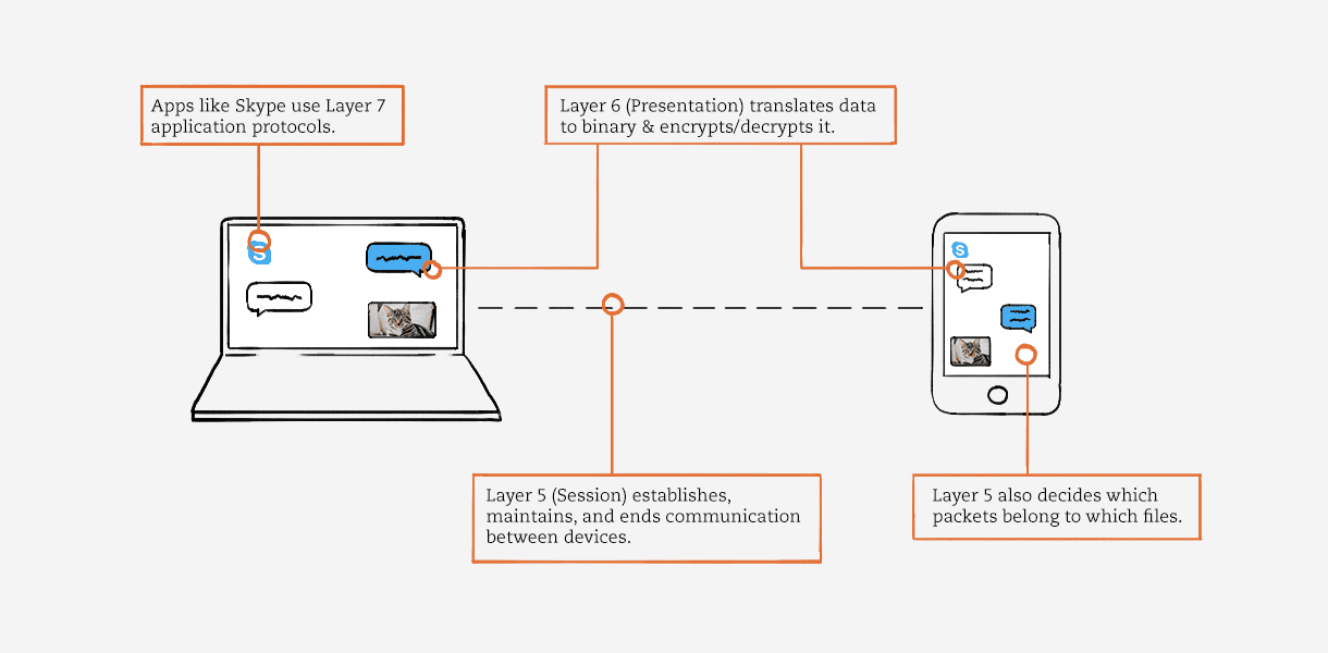
Let’s suppose you’re using Skype on a laptop. You’re messaging your friend, who’s using Skype on their phone from a different network.
Skype, as a network-connected application, uses Layer 7 (Application) protocols like Telnet. If you send your friend a picture of your cat, Skype would be using the File Transfer Protocol (FTP).
Layer 6 (Presentation) receives application data from Layer 7, translates it into binary, and compresses it. When you send a message, Layer 6 encrypts that data as it leaves your network. Then it decrypts the data when your friend receives it.
Applications like Skype consist of text files and image files. When you download these files, Layer 5 (Session) determines which data packets belong to which files, as well as where these packets go. Layer 5 also establishes, maintains, and ends communication between devices.
Transport and Network Layers
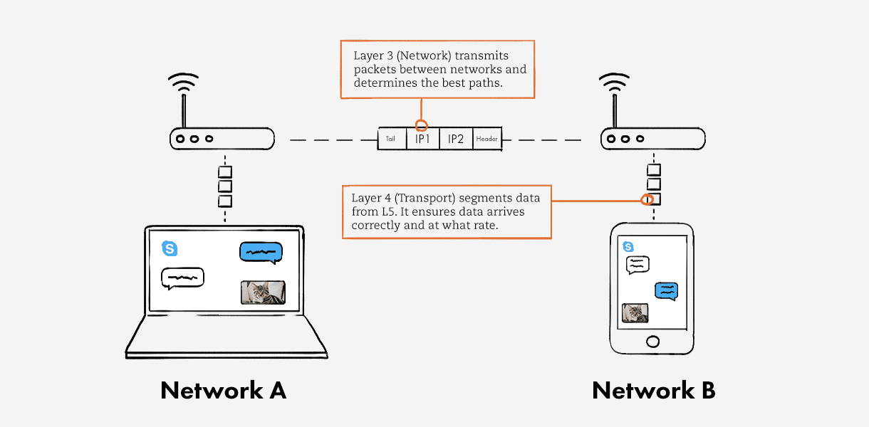
Layer 4 (Transport) receives data from Layer 5 and segments it. Each segment, or data unit, has a source and destination port number, as well as a sequence number. The port number ensures that the segment reaches the correct application. The sequence number ensures that the segments arrive in the correct order.
This layer also controls the amount of data transmitted. For example, your laptop may be able to handle 100 Mbps, whereas your friend’s phone can only process 10 Mbps. Layer 4 can dictate that the server slow down the data transmission, so nothing is lost by the time your friend receives it. But when your friend sends a message back, the server can increase the transmission rate to improve performance.
Lastly, Layer 4 performs error-checking. If a segment of data is missing, Layer 4 will re-transmit that segment.
TCP and UDP are both very well-known protocols, and they exist at Layer 4. TCP favors data quality over speed, whereas UDP favors speed over data quality.
Layer 3 (Network) transmits data segments between networks in the form of packets. When you message your friend, this layer assigns source and destination IP addresses to the data segments. Your IP address is the source, and your friend’s is the destination. Layer 3 also determines the best paths for data delivery.
Data Link and Physical Layers
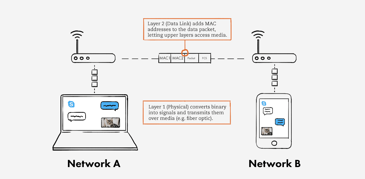
Layer 2 (Data Link) receives packets from Layer 3. Whereas Layer 4 performs logical addressing (IPv4, IPv6), Layer 2 performs physical addressing. It adds sender and receiver MAC addresses to the data packet to form a data unit called a frame. Layer 2 enables frames to be transported via local media (e.g. copper wire, optical fiber, or air). This layer is embedded as software in your computer’s Network Interface Card (NIC).
In short, Layer 2 allows the upper network layers to access media, and controls how data is placed and received from media.
Hardware—the things you can actually physically touch—exist at Layer 1 (Physical). This layer converts the binary from the upper layers into signals and transmits them over local media. These can be electrical, light, or radio signals; it depends on the type of media used. When your friend receives the signals, they’re decapsulated, or translated back into binary and then into application data so your friend can see your message.
In Conclusion
Network layers help us understand how data moves from something human-readable, to computer-readable, to a transmitted signal, and back again.
In this blog, we covered the simple example of a Skype conversation. But real-world networks are far more complex, with tons of data moving around via these network layers. IT teams can glean insights from that data that make it possible to optimize and secure the networks they manage.
Interested in learning more about how to leverage data collected from your network? Our blog on understanding network observability is a great place to start.
Speak to a technical representative