One of the biggest questions being asked of IT professionals is, “Are we using our bandwidth to its fullest potential”? Of course we have many tools to help answer that question, fortunately Cisco has developed another to add to our arsenal. With Cisco’s Intelligent WAN (IWAN) you can give your organization the ability to deliver an uncompromised experience over any connection.
With companies rapidly growing and expanding their reach via remote locations and globalization, the WAN has become a core route of communication between these remote offices and employees/customers around the world. While companies are expanding, we’ve also seen a push for data center consolidation which means applications are being moved to core data centers or the cloud. What does this mean for IT professionals? It means the WAN now plays a critical role in business productivity, and survivability is dependent on the availability and performance of the network. In the past, the best way to get reliable and predictable performance between sites was to take advantage of a private WAN using MPLS or leased line service. Which as most of us know can be very expensive and not always cost effective.
Let’s take a look at what Cisco IWAN is all about and what it can offer us in terms of optimizing our WAN traffic. Cisco’s IWAN is a system that augments collaboration and cloud applications performance, while shrinking the operating cost of your WAN. IWAN can enable organizations to deliver an uncompromised experience over any connection. With the IWAN solution, traffic is dynamically routed based on applications SLA, endpoint type and network conditions all to deliver the best quality experience. In short, IWAN allows you to:
- Augment your network with lower-cost connectivity options, like the Internet
- Realize the cost benefits of provider flexibility and higher WAN utilization
- Offload the corporate WAN with application optimization, intelligent caching, and highly secure direct Internet access.
IWAN is built heavily on Performance Routing v3 (PfRv3), which is Cisco’s next generation Intelligent Path Control. The latest release of IOS 15.5(3)M and IOS-XE 3.16 are the recommended releases to support PfRv3.
IWAN is comprised of two major Cisco IOS components, a Master Controller (MC) and a Border Router (BR). The MC is the policy decision maker. Generally at larger sites the MC will be a standalone chassis. For smaller branch locations, the MC is usually configured on the same platform as the BR. BR’s are in the data forwarding path. They collect data from their Performance Monitor cache, perform a small amount of data aggregation, and will influence the packet forwarding path as directed by the sites local MC to manage user traffic. Each site in the PfR Domain must include a local MC and at least one BR.
In an IWAN domain there are five different roles a device can be:
- Hub Master Controller (Hub MC) – This is the MC at the hub site that acts as MC for the site and makes optimization decision for that site and provides the Path Control policies for all the other MCs. The Hub MC contains the logical PfR domain controller role
- Transit Master Controller (Transit MC) – This is the MC at transit sites and makes optimization decision for that site. There is no policy configuration on Transit MCs because they receive their policy from the Hub MC
- Branch Master Controller (Branch MC) – The branch MC is the MC for branch sites, and makes optimization decisions for that branch site.. There is no policy configuration on branch MCs because they receive their policy from the Hub MC
- Transit Border Router (Transit BR) – The border controller at a Hub or Transit site. WAN interface terminates in the BRs. PfR is enabled on these interfaces. At the time of this writing, only one WAN interface is supported on a BR. This limitation is overcome by using multiple BRs devices
Hub Master Controller
The Hub MC is located at the hub site in the IWAN topology and it’s important to note that the Hub MC actually supports two different roles:
- It acts as a Local MC for the site and will peer with the local BRs to control them. This roles is similar to a Transit MC
- It also acts as a Global Domain Controller with PfR policies for the entire IWAN domain and peers with all MCs in the domain
The Hub MC should run as a standalone platform on a physical device or as a virtual machine. Configuring the MC for hub will include the following:
- Define the IWAN Domain Name
- Define the VRF
- Identify the Router as the Hub MC
- Define the Source Interface for PfR Communication
- Define Password (Optional)
- Define PfR domain policies – this will be explained in the PfR policies section
Example Hub MC configuration:
domain IWAN
vrf default
master hub
source-interface Loopback0
enterprise-prefix prefix-list ENTERPRISE_PREFIX
site-prefixes prefix-list SITE_PREFIX
collector 10.151.1.95 port 2055
!
ip prefix-list ENTERPRISE_PREFIX seq 10 permit 10.0.0.0/8
ip prefix-list SITE_PREFIX seq 10 permit 10.1.0.0/16
!
Hub Border Routers
A Hub BR is a border controller at a hub-site. This is the device where the WAN interface terminates. This is the interface we’ll want PfR enable on. There can be one or more Hub BRs per DMVPN transport for horizontal scaling. It’s important to note that WAN tunnel interfaces aren’t automaticall discovered and are manually configured.
On the Hub BR, PfR must be configured with:
- The address of the local MC
- The path name on external interfaces
- The path identifier on external interfaces. This identifier must be unique per site.
The BR will register to their local MC with their external interface definition together with their path name and identifier. You have the option to use the global routing table or alternatively you can define your own VRFs for hub border routers.
Example Hub BR configuration for MPLS:
!
domain IWAN
vrf default
border
source-interface Loopback0
master 10.1.0.10
!
interface tunnel100
domain IWAN path MPLS path-id 1
!
Example Hub BR configuration for Internet:
!
domain IWAN
vrf default
border
source-interface Loopback0
master 10.1.0.10
!
interface tunnel200
domain IWAN path INET path-id 2
!
Transit Master Controller
The Transit MC is located at each Transit site in an IWAN topology. Similar to the Hub MC the Transit MC should run as a standalone platform on a physical device or as a virtual machine. A Transit MC needs to peer with the Domain Controller (Hub MC) to receive the policies, monitor configurations and global parameters.
Configuring the Transit MC will include the following:
- Define the IWAN Domain Name
- Define the VRF
- Identify the router as the Transit MC and define the POP-ID
- Define the Source Interface for PfR Communication
- Configure the Hub MCDefine Password (Optional)
Example Configuration for Transit MC:
domain IWAN
vrf default
master transit 1
source-interface Loopback0
site-prefixes prefix-list SITE_PREFIX
hub 10.1.0.10
!
ip prefix-list SITE_PREFIX seq 20 permit 10.2.0.0/16
!
!
Transit Border Routers
A Transit BR has exactly the same role and behavior as the Hub BR. This is the device where the WAN interface terminates on a central site or datacenter. This is the interface where PfR will be enabled. Just like the Hub BR, there can be one or more Tansit BRs per DMVPN transport for horizontal scaling. The WAN interfaces will also need to be manually configured.
On the Transit BR, PfR must be configured with:
- The address of the local MC
- The path name on external interfaces
- The path identifier on external interfaces. Must be unique per site.
Example Transit BR configuration for MPLS:
!
domain IWAN
vrf default border
source-interface Loopback0
master 10.2.0.20
!
interface tunnel100
domain IWAN path MPLS path-id 1
!
Example Transit BR configuration for Internet:
!
domain IWAN
vrf default
border
source-interface Loopback0
master 10.2.0.20
!
interface tunnel200
domain IWAN path INET path-id 2
!
Branch Routers
The MC at a branch site typically doesn’t require a dedicated router to act as a MC. This implies that at least one branch site router will contain the MC and the BR roles on it. If a branch site has two routers for resiliency, the MC is typically connected to the primary transport circuit. A Branch MC receives the PfR policies, performance monitored instances and global parameters from the Hub MC. The branch MC acts as the MC for that site, making optimization decisions.
Configuring the MC for a branch site will include the following:
- Define the IWAN Domain Name
- Define the VRF
- Identify the router as the Branch MC
- Define the Source Interface for PfR Communication
- Configure the Hub MC
- Define Password (Optional)
Example configuration for a single branch where the MC and BR are collocated on the platform:
!
domain IWAN
vrf default
border
source-interface Loopback0
master local
master branch
source-interface Loopback0
hub 10.1.0.10
!
Example configuration of a dual CPE branch, where the MC and BR are collocated on the primary router (R1) and another BR is defined on a separate router (R2):
!
domain IWAN
vrf default
border
source-interface Loopback0
master local
master branch
source-interface Loopback0
hub 10.1.0.10
!
R2 configuration (Includes the BR definition that points to the site MC):
!
domain IWAN
vrf default
border
source-interface Loopback0
master 10.5.0.51
!
PfR Policies
PfR policies are the rules that determine how to monitor and control traffic. PfR policies are global to the IWAN domain and are defined in the Hub MC and the pushed out to Branch and Transit MCs using the SAF infrastructure.
PfR policies include:
- Administrative Policies. These policies specify constraints such as path preference or Transit Site preference. Critical applications or media applications will be forwarded over a primary path, which is MPLS and only failover to the secondary path INET if performance is outside of the policy.
- Performance Policies. Specify constraints such as delay, jitter and loss threshold. This defines the boundaries in which an application is correctly supported and the end user experience is good.
- Load Balancing policy. When load balancing is enabled, all the traffic that falls in the default class is load balanced
- Monitor-interval. This configures the interval time that will define the monitoring interval on ingress monitors
Performance Policies:
PfR policies can be configured on a per application basis or by DSCP QoS markings. Policies are put into groups called a class. Class groups are primarily used to define a classification order priority, but also to group all traffic that has the same administrative policies. Each class group is assigned a sequence number and PfR will monitor the policies by following the sequence number.
A few rules that are definitely worth mentioning:
- PfR does not support mixing and matching of DSCP and application-based policies in the same class group.
- PfR does support the use of predefined policies from the template or user created custom policies.
- Traffic that does not match any of the class group match statements will fall into a default bucket called the default class.
Load Balancing:
The Load-Balancing configuration is used to define the behavior of all the traffic that falls into the default class. When load balancing is enabled, Traffic Classes that fall into the default class are load balanced. When load balancing is disabled, PfRv3 deletes this default class and those Traffic Classes are forwarded based on the routing table information.
A very common example includes the definition of a class group for voice, interactive video and critical data. For simplicities sake, this is what we’ll use as an example. However, more complex policies can be defined with the use of application names.
Example policy based on DSCP that uses custom thresholds. This would be defined on the Hub MC for the domain:
!
domain IWAN
vrf default
master hub
monitor-interval 4 dscp ef
monitor-interval 4 dscp af41
monitor-interval 4 dscp cs4
monitor-interval 4 dscp af21
load-balance
advanced
channel-unreachable-timer 4
collector 10.151.1.95 port 2055
class VOICE sequence 10
match dscp ef policy custom
priority 2 loss threshold 5
priority 1 one-way-delay threshold 150
path-preference MPLS fallback INET
class VIDEO sequence 20
match dscp af41 policy custom
priority 2 loss threshold 5
priority 1 one-way-delay threshold 150
match dscp cs4 policy custom
priority 2 loss threshold 5
priority 1 one-way-delay threshold 150
path-preference MPLS fallback INET
class CRITICAL sequence 30
match dscp af21 policy custom
priority 2 loss threshold 10
priority 1 one-way-delay threshold 600
path-preference MPLS fallback INET
!
You can select an existing template as domain type for a policy or use a custom mode. The available templates for comain policy types include:
- best-effort
- bulk-data
- low-latency-data
- real-time-video
- scavenger
- voice
- custom – Defines customized user-defined policy values.
Now that we have a high level overview of Cisco’s IWAN technology, let’s look at how we can monitor the traffic behavior via Flexible NetFlow. FNF can be used to check active flows between data centers and branch offices. The process for configuring FNF will be identical to what we’re used to from most Cisco devices:
Create your Flow Record:
!*******************************
! FLOW RECORD
! What data do I want to meter?
! First define the flow record that you want.
! ‘match’ is used to identify key fields, ie, those fields used to define what a flow is
! ‘collect’ is used to define what fields we want to monitor
!
flow record RECORD-STATS
match ipv4 dscp
match ipv4 protocol
match ipv4 source address
match ipv4 destination address
match transport source-port
match transport destination-port
match interface input
match flow direction
collect routing next-hop address ipv4
collect counter bytes
!
Create the Flow Monitor:
!*******************************
! FLOW MONITOR
! Creates a new NetFlow cache
! Attach the flow record
! Exporter is attached to the cache
! Potential sampling configuration
!
flow monitor MONITOR-STATS
cache timeout inactive 60
cache timeout active 60
cache timeout update 1
record RECORD-STATS
!
Apply the Flow Monitor to an interface:
!
interface Tunnel 100
description — TO BORDER ROUTERS —
ip flow monitor MONITOR-STATS input
ip flow monitor MONITOR-STATS output
!
Let’s take a look at how this traffic is reported on within our favorite NetFlow Collector:
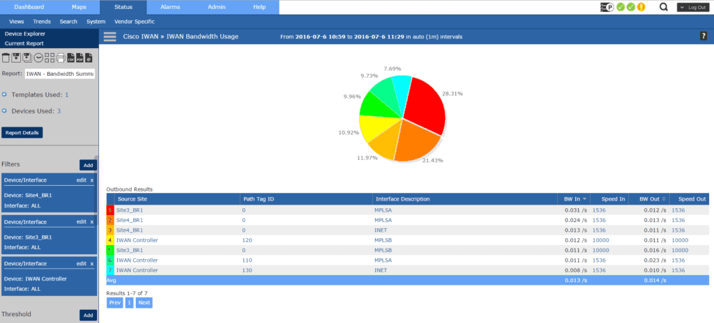
The Bandwidth Usage report will tell us the overall utilization from each site. The interface description, which tells us the path. As well as the bandwidth rate in and out of the site.
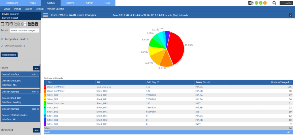
With the Route Changes report we get to see each site, the Path Tag ID, IWAN Circuit being used and also the number of route changes for our given time frame.
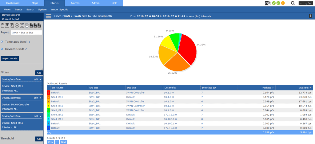
Our Site to Site Bandwidth report gives us very useful information. Here we’re presented with the Border Router being used, the source site, destination site, destination prefix (subnet), Interface ID and the amount of throughput in bandwitdth.
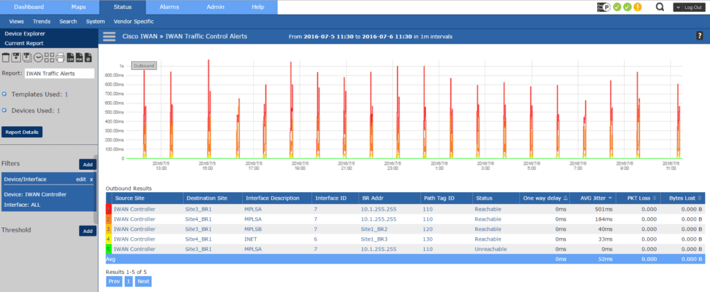
The Traffic Control Alerts report gives us the same information we’re used to, which site is talking to which site. However the information is augmented by also giving us the status, one way delay (which is the time it takes one packet to be transmitted across a network from source to destination. This is different than Round Trip Time), average jitter, as well as any packet and data loss.
Overall, coupling Cisco’s IWAN topology with NetFlow analysis provides us unprecedented control and analysis over our site to site traffic. For more information about Cisco IWAN technology, review their documentation here.


