In my previous blog, I discussed what Cisco IWAN is, and the benefits it brings to multi-branch offices connected to an MPLS WAN. Today’s topic continues that discussion by explaining the process of configuring Cisco Dynamic Multipoint VPN (DMVPN).
To recap my previous post, DMVPN is an efficient solution for dynamic secure overlay networks. DMVPN combines the following technologies:
- Multipoint GRE (mGRE)
- Next-Hop Resolution Protocol (NHRP)
- Dynamic Routing Protocol (EIGRP, RIP, OSPF, BGP)
- Dynamic IPsec encryption
- Cisco Express Forwarding (CEF)
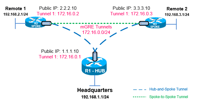
Before I begin, I want to outline the network. The DMVPN will be configured with two remote locations (SPOKE) and a central headquarters (HUB). The two remote locations will be connected to the central headquarters and will also have a spoke-to-spoke connection.
Step 1: Configuring Cisco DMVPN HUB
After you have configured your router’s LAN and WAN interfaces create the mGRE tunnel interfaces.
interface FastEthernet0/0
 description LAN-Network
 ip address 192.168.1.1 255.255.255.0
 duplex auto
 speed auto
!
interface FastEthernet0/1
 description WAN-Network
 ip address 1.1.1.10 255.255.255.0
 duplex auto
 speed auto
Proceed by configuring the Tunnel0 interface. The sections in bold are important details (they are what make the change different from a typical tunnel interface configuration). If you are familiar with GRE tunnels, you will notice that tunnel destination has been replaced by tunnel mode gre multipoint, which designates this tunnel as a multipoint GRE tunnel.
interface Tunnel0
 description mGRE - DMVPN Tunnel
 ip address 172.16.0.1 255.255.255.0
 no ip redirects
 ip nhrp authentication firewall
 ip nhrp map multicast dynamic
 ip nhrp network-id 1
 tunnel source 1.1.1.10
 tunnel mode gre multipoint
Step 2: Configure Cisco DMVPN Remote 2 and Remote 3
Now that we have configured the HUB, we need to configure the two remote routers.
Configuring Remote 2
We need to configure the LAN and WAN interfaces first.
interface FastEthernet0/0
 description LAN-Network
 ip address 192.168.2.1 255.255.255.0
 duplex auto
 speed auto
!
interface FastEthernet0/1
 description WAN-Network
 ip address 2.2.2.10 255.255.255.0
 duplex auto
 speed auto
Now configure the tunnel.
interface Tunnel0
 description R2 mGRE - DMVPN Tunnel
 ip address 172.16.0.2 255.255.255.0
 no ip redirects
 ip nhrp authentication firewall
 ip nhrp map multicast dynamic
 ip nhrp map 172.16.0.1 1.1.1.10
 ip nhrp map multicast 1.1.1.10
 ip nhrp network-id 1
 ip nhrp nhs 172.16.0.1
 tunnel source FastEthernet0/1
 tunnel mode gre multipoint
Configuring Remote 3
Set up the LAN and WAN Interfaces.
interface FastEthernet0/0
description LAN-Network
 ip address 192.168.3.1 255.255.255.0
 duplex auto
 speed auto
!
interface FastEthernet0/1
 description WAN-Network
 ip address 3.3.3.10 255.255.255.0
 duplex auto
 speed auto
Then configure the tunnel.
interface Tunnel0
 description R3 mGRE - DMVPN Tunnel
 ip address 172.16.0.3 255.255.255.0
 no ip redirects
 ip nhrp authentication firewall
 ip nhrp map multicast dynamic
 ip nhrp map 172.16.0.1 1.1.1.10
 ip nhrp map multicast 1.1.1.10
 ip nhrp network-id 1
 ip nhrp nhs 172.16.0.1
 tunnel source FastEthernet0/1
 tunnel mode gre multipoint
Step 3: IPSec Configuration
To secure the traffic (i.e. ensure traffic is not sent in clear text), we must add IPSec.
crypto isakmp policy 1
encr 3des
hash md5
authentication pre-share
group 2
lifetime 86400
!
crypto isakmp key plixer address 0.0.0.0
!
crypto ipsec transform-set TS esp-3des esp-md5-hmac
!
crypto ipsec profile protect-gre
set security-association lifetime seconds 86400
set transform-set TS
!
interface Tunnel 0
tunnel protection ipsec profile protect-gre
Note: when using dynamic IP addresses, 0.0.0.0 0.0.0.0 must be used.
Remote 2 and Remote 3
crypto isakmp policy 1
encr 3des
hash md5
authentication pre-share
group 2
lifetime 86400
!
crypto isakmp key firewall.cx address 0.0.0.0 0.0.0.0
!
crypto ipsec transform-set TS esp-3des esp-md5-hmac
!
crypto ipsec profile protect-gre
set security-association lifetime seconds 86400
set transform-set TS
!
interface Tunnel 0
tunnel protection ipsec profile protect-gre
Again, we use 0.0.0.0 0.0.0.0 as the isakmp peer address. While the hub’s public IP address is known, keep in mind R2 and R3 can build dynamic VPN tunnel between them. Taking into consideration that their public IP address is dynamic, it is imperative to use 0.0.0.0 0.0.0.0 for the remote peer.
Once the IPSec configuration is in place, use the command show crypto session to verify.
Step 4: Routing between DMVPN mGRE
The last thing to do is enable routing in the DMVPN network.
HUB
ip route 192.168.2.0 255.255.255.0 172.16.0.2
ip route 192.168.3.0 255.255.255.0 172.16.0.3
Remote 2
ip route 192.168.1.0 255.255.255.0 172.16.0.1
ip route 192.168.3.0 255.255.255.0 172.16.0.3
Remote 3
ip route 192.168.1.0 255.255.255.0 172.16.0.1
ip route 192.168.2.0 255.255.255.0 172.16.0.2
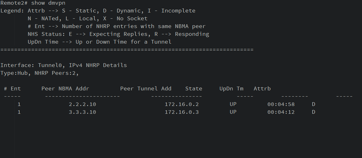
And that’s it! You’ve successfully configured your DMVPN network. To verify, issue show dmvpn on the router.